

 no reviews
Multimeter purchasing advice: how to choose the right product
- What you need to know
- A multimeter is a measuring device for various electrical quantities.
- Most devices can measure voltage, current and resistance.
- With the help of a multimeter, you can check the functionality of electronic devices.
The all-in-one measuring device
The multimeter is the standard measuring device for all electronics and electrical engineers. It displays various important measured variables, for example voltage, current and resistance. For professionals, such a device is indispensable in everyday work, but it can also be interesting for private use, for example for hobbyists and do-it-yourselfers with specialist knowledge. Those who are less experienced can use a multimeter to determine, for example, whether the fault in a non-functioning device lies in the device itself or in the power supply.
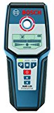
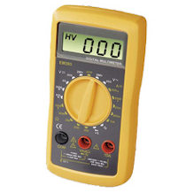
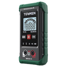
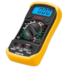
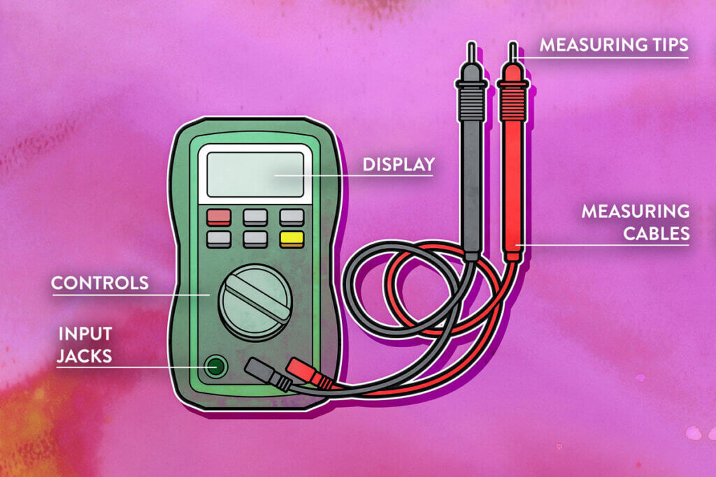
The analogue multimeter with needle display is hardly to be found nowadays. It has been almost completely replaced by the digital multimeter. This is more accurate and easier to read. In addition to the display for reading the measured value, a multimeter has various buttons for selecting the functions and a rotary switch for selecting the measurand to be tested. The measurement is carried out with the help of two test probes that are connected to the multimeter. They establish the conductive connection from the device to the test object.
What to look for when buying a multimeter
A multimeter is undoubtedly practical, but it remains a device that people without the appropriate specialist background do not often have use for. For occasional checking, a device that measures voltage, current and resistance is sufficient. If you are not an expert, you should definitely pay attention to the auto-range function, which saves users a lot of work.
The most important measuring functions
The three basic measuring functions are voltage, current and resistance. Many high-quality multimeters are capable of other measuring modes, but these are only useful for electronics hobbyists and professionals. These include, for example, capacitance measurement and diode test.
Voltage
The formula symbol for voltage is U, the unit is volts (V). Voltage describes the “strength” of a voltage source and is the cause of the current that transports an electric charge. Put simply, it can be understood as the drive of the electric current. In a voltage source, there is an excess of electrons at the negative pole and a shortage of electrons at the positive pole. The greater the difference, the higher the voltage. The voltage is measured by holding the two test prods of the multimeter to the two contact points between which the voltage is to be determined.
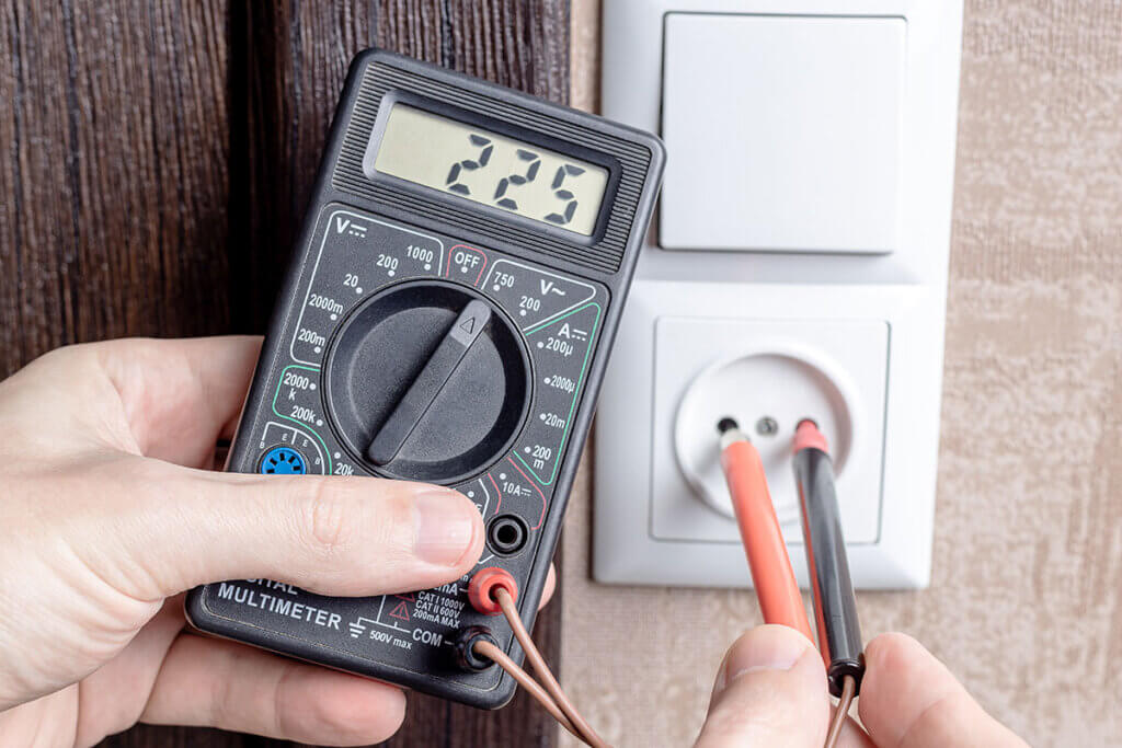
Important: The difference between DC and AC voltage must be taken into account when measuring, because if the wrong type of voltage is selected, the result will not be meaningful. For example, there is alternating voltage on the sockets in flats. Good multimeters recognise DC and AC voltage automatically and adjust themselves.
Current
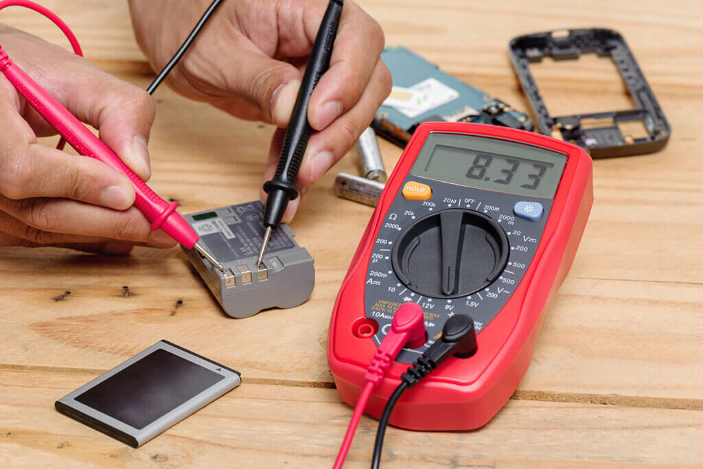
Electric current flows when both poles of a voltage source are conductively connected to each other via a consumer. The formula symbol for current is I and the unit is amperes (A). The amount of current depends on the voltage at the voltage source and the resistance of the consumer. Most multimeters are only able to measure the current if they are part of the circuit themselves. To do this, the circuit must be disconnected and the multimeter connected in series.
Resistance
Resistance measurement is one of the basic functions of multimeters. The formula symbol for resistance is R, the unit is Ohm (Ω). A resistance measurement is used to determine the voltage required to allow an electric current to flow through a conductor. This is how lines, switches and fuses can be checked. The measurement is made by contacting the two points between which the resistance is to be measured.
Capacitance measurement
The capacitance measurement is used to check the functionality of capacitors. During the measurement, the multimeter charges the capacitor to be tested with constantly changing polarity. Due to the charging current flowing during this process, the measuring device can determine the capacitance of the capacitor. The unit for electrical capacitance is Farad (F).
Diode measurement
The diode test is used to check the PN transitions of diodes. In functioning diodes, the semiconductor allows current in one direction and blocks it in the other direction. A defective diode does not conduct the current at all, or allows it to flow in both directions. Furthermore, the threshold voltage of a diode can be determined.
Continuity measurement
The continuity test can be used to determine whether two measuring points are electrically connected to each other. In principle, a resistance measurement is sufficient for this, but some devices have a function specifically designed for this purpose.
Basic accuracy
The basic accuracy is a specification for error limits. It is the largest permissible deviation that may occur during a measurement. Depending on the application, it is more or less important. On AC lines, the voltage can vary by up to 5 percent. It is advisable to always keep this error limit in mind.
Most manufacturers of multimeters state the basic accuracy of their device, but this is usually only the smallest possible error. In addition, external influences such as temperature are often not taken into account when determining the accuracy. There are also no binding specifications for basic accuracy. It is therefore a quality feature that should be treated with some caution.
Important components and accessories
Multimeters have a central rotary switch with which the desired measuring unit is selected. Here you may need to brush up on your knowledge of physics if you are no longer familiar with all the units. The actual measurement is made by means of the two measuring tips, which are held against the test object.
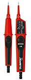
Test leads
The test leads with the test prods make the use of the multimeter possible. They establish the connection between the multimeter and the test object. As a rule, one black and one red lead are included in the delivery. The black lead must be plugged into the connection with the minus sign or the labelling “COM”. To avoid confusion, this connection is also often coloured black. The red test lead belongs in the plus connection, which sometimes also bears a V for volts or Ω for ohms. In short: Red is for the positive terminal, black for the negative terminal. This is important to know if the circuit under test is not marked accordingly.
At their ends, the two leads have a measuring tip that is held to the measuring points. Multimeter sets often contain other leads that are equipped with so-called crocodile clips, for example. They make measuring on wires easier because they can be easily clamped on. Good multimeters also have a temperature sensor with which temperatures can be measured. Some high-quality devices have a so-called probe. This allows measurements to be taken even on fine electronics for which needles and clamps would be too coarse.
Control panel with selector switch
In the centre of every digital multimeter is the rotary selection switch. Here you can select the different types of measurements and measuring ranges. Next to it are control buttons for other functions that are sometimes available, for example, for the backlight.
At first glance, inexpensive devices in particular seem to have a lot of setting options. This is because each measuring range has to be set by the user and constant readjustment is necessary. High-quality multimeters have tidier setting options, but they do not have fewer functions. Instead, they have the so-called auto-range, which automatically selects the appropriate measuring range – i.e. the decimal places in the display. This eliminates the need for time-consuming fine adjustment. The auto-range function is particularly practical when the measuring range is not known and relieves laypersons of the tedious adjustment. If necessary, manual adjustment is usually still possible.
Before measuring, the selection switch must be set to the appropriate unit. Measuring voltage, current and resistance is part of the basic repertoire of every multimeter. As a rule, however, a few other measurements can be made. The following units are usually found on a multimeter control panel:
- V for volt: the physical unit for electrical voltage.
- A for ampere: the unit for electric current; the same applies to microamperes (µA), but reduced by a factor of 1,000
- Ω for Ohm: the unit of electrical resistance
- Hz for Hertz: the unit of frequency, i.e. the number of repetitive processes in a periodic signal.
- µF for microfarad: the unit farad, reduced by a factor of 1,000, which stands for the electrical capacitance of capacitors.
- °C for temperature: the unit according to the Celsius scale.
Connection sockets
On a multimeter, the connection sockets are located in the lower area of the front. The number of these sockets is between two and four. The following two connections are required in any case for measuring with a multimeter:
- Minus pole or earth: Black socket labelled COM or GRN.
- Positive pole: Red socket labelled INPUT or IN.
High-quality multimeters have three sockets. Two of them are used to measure current; one for currents in the milliamp range and the other for high currents in the 10 A range. In devices with four sockets, the inputs for amperage are completely separated from those for other measured quantities, which reduces the risk of incorrect operation.
Measurement category
The measuring categories provide information on the areas of application in which a measuring instrument can be used without risk. The IEC 61010-2-030 standard defines four categories. This is to prevent users from being endangered by incorrect use, for example by short circuits, burns or sparks. If the measurement category is not specified by the manufacturer, the classification CAT I applies.
| Measurement category | Field of application |
| CAT I | Measurements on circuits that do not have a direct connection to the mains, i.e. are battery-operated, for example protection class 3 devices and 12/24 volt car electrics. |
| CAT II | Measurements on circuits with a direct plug connection to the low-voltage mains, e.g. household appliances. |
| CAT III | Measurements within the building installation, for example stationary consumers with non-plug-in connection, distribution connection, permanently installed equipment with distribution board. |
| CAT IV | Measurements at the source of the low-voltage installation, e.g. meter, low-voltage overhead line, house junction box. |
In addition to the measurement category, a maximum voltage can also be specified. The device is then marked CAT III 600 V, for example. In the household, however, such high voltage ranges are rarely encountered. Most household appliances have a voltage of up to 230 volts. A device marked CAT III 600 V is therefore sufficient for all DIY work. Work that would require a CAT IV device may only be carried out by trained electricians anyway. Even measurements within the building installation, for which CAT III devices are suitable, should better not be carried out by persons without specialist knowledge.
Safe handling of the multimeter
Working with electrical installations always involves risks, so never go about it unprepared. Lay people can use a multimeter to check the voltage on a household appliance, test the cables of a ceiling light or check a socket. Any work beyond this should be left to a professional.
Before using the multimeter, check for damage to the unit itself or to the test leads and tips. Furthermore, make sure that all plugs are firmly seated in the sockets. After the visual inspection, make sure that the multimeter is working properly. To do this, measure at a known voltage source or ideally at a test unit. The latter is a battery-operated voltage source in pocket format. It allows you to test the multimeter safely.
Electrocution happens when the human body becomes part of an electric circuit. Voltages as low as 30 volts can be dangerous. An ordinary socket has a voltage of 230 volts. If you are taking a measurement on a live electrical system, you should wear special protective gloves and stand on or place an insulating mat underneath.
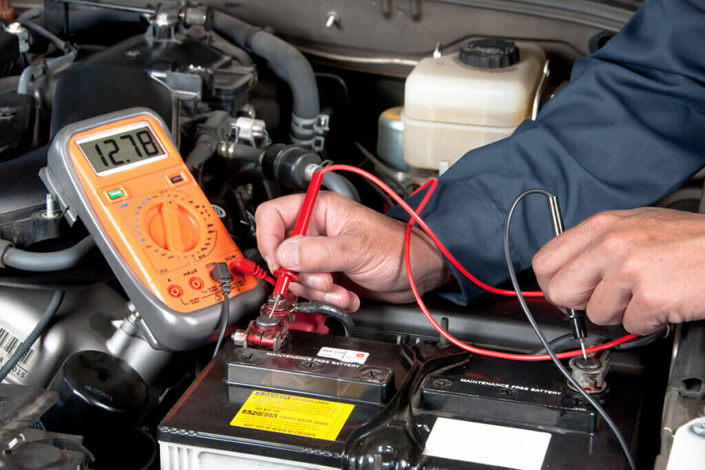
Application example: measuring voltage
Perhaps the most common application scenario for a multimeter is during renovation work. Here it is often unavoidable that lamps or sockets have to be dismantled. After removing the corresponding fuse, it is important to check the connections for residual voltage or leakage current.
In order to determine the voltage, the correct voltage type (AC or DC) and the appropriate measuring range must first be set on the multimeter. If the values cannot be estimated accurately, it is better to set a measuring range that is as high as possible and to switch down in the course of the measurement in order to obtain more accurate results. A multimeter with an auto-range function simplifies this adjustment considerably. Here, you only have to set volts for voltage.
Now connect the measuring leads and apply the measuring tips. The black test lead of the negative pole is plugged into the COM socket, the red test lead of the positive pole into the INPUT socket. The voltage is then checked by applying the measuring tips to the object. The peaks must always be applied parallel to the load or supply. The voltage can now be read in volts on the display.
Image 1: © FinalCheck | Image 2: © NorGal / stock.adobe.com | Image 3: © Andrii / stock.adobe.com | Image 4: © FinalCheck | Image 5: © cherylvb / stock.adobe.com